A Retro Go PCB for the LEGO Gameboy Model
Version 2.0 (Functional, but still need some hardware fine tuning)
About:
I recently started learning PCB design and decided to embrace the Dunning–Kruger effect by diving straight into the deep end: converting the LEGO Game Boy model into a fully functional Game Boy (emulator). This is an ongoing project that still requires improvements. I have no current plans to sell the design, but I’ll share it on GitHub for anyone interested in building one.
Downloads:
https://github.com/gazaki/Retro-Le-Go-Boy
How to compile:
- Download retro-go from https://github.com/ducalex/retro-go/blob/master/BUILDING.md
- Download the target files from github, and move them into a copy of retro-go in “Retro-Go/components/retro-go/targets/retro-le-go-boy”
- if using a N16R8 consider changing settings in sdkconfig
CONFIG_ESPTOOLPY_FLASHSIZE_8MB=n CONFIG_ESPTOOLPY_FLASHSIZE_16MB=y CONFIG_ESPTOOLPY_FLASHSIZE=”16MB” - Compile using the guide on https://github.com/ducalex/retro-go/blob/master/BUILDING.md
- Or download the precompiled .img files for either N8R8 or N16R8 and upload them.
Ordering PCB:
The Gerber file for ordering on JLCPCB is here https://github.com, order details that are not standart are:
- Layers: 2
- Different Design: 5
- Mark on PCB: Order Number(Specify Position)
Getting components:
Components can be seen in the ibom.html file
For convenience i have also linked to the components i used here:
- Most components are from DigiKey so i have made a list of the components i bought here https://github.com (some may be out of stock, but DigiKey normally suggest alternatives)
- Screen 1X: https://www.aliexpress.com
- Buttons 8X: https://www.aliexpress.com
3D Printed Files:
- All stl files can be found here: https://github.com
- To assemble them you also need 4x M3x16 and a M3 drill tap.
- “Print Holder.stl” is for holding the print when soldering them together so they have the right distance.
To Do’s and Improvements:
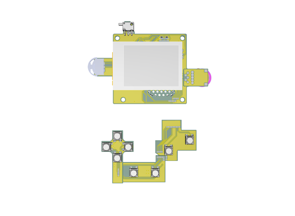
- Remove top piece of on button PCB (design supported two different buttons to test out and one failed to work, so i should be removed)
- Make a Ribbon cable to connect button PCB’s with main board (currently you need to solder so many wires)
- Change layout of power supply (currently the screens brightness will dim if you turn the speaker volume up to loud)
- Find buttons with less travel for the D-Pad (the cross plate moves to much and can slightly dislodge the 1×4 flat plate underneath it)
- Move volume pot-meter a couple of millimeters to the left (just for visual)
- Change i2s to mono output, (thought i could do it in software, but i should have done it on hardware by (theoretically) adding a 634kΩ on SD_MODE to 3v3 on MAX98357AETE+T
Tools used:
- Solder Iron: TS-100
- Hot Plate: MHP50
- 3D Printer: Ender 3 V3 SE
- Olympus SZ51 Microscope
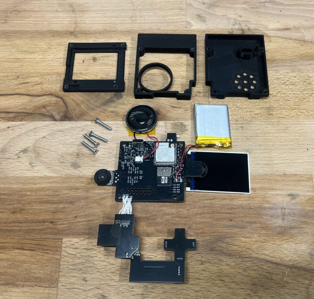
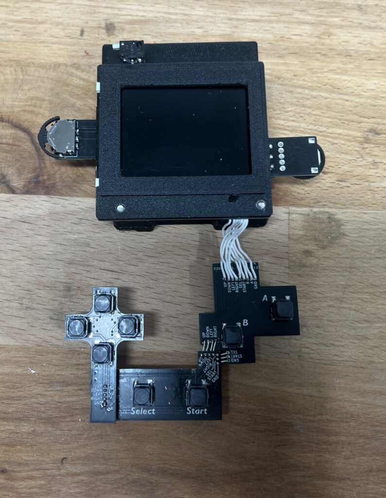
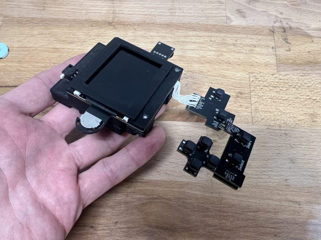
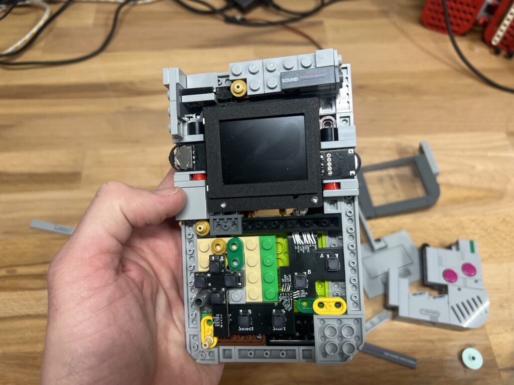
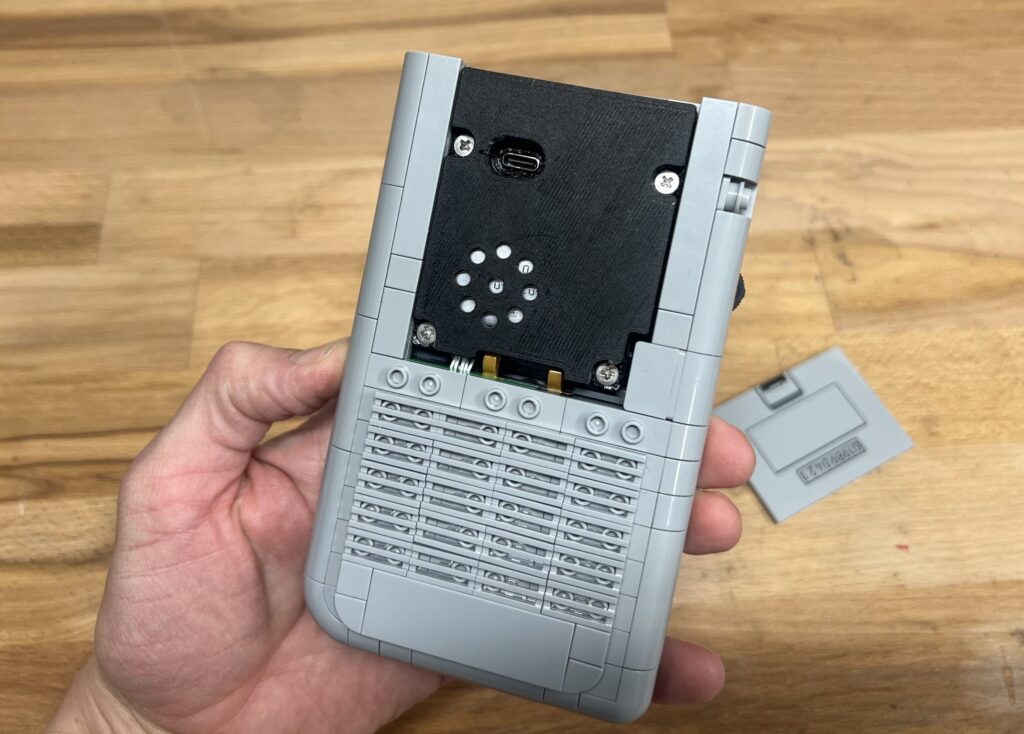
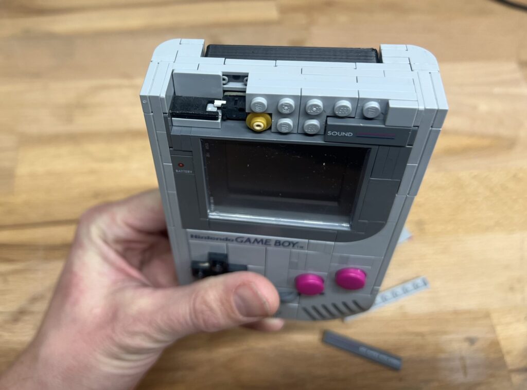
Pictures: